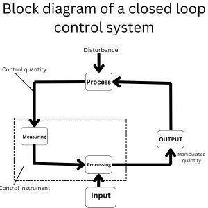
Closed Loop Control For Cnc Machines Pdf Block diagram of a closed loop control system published by rajib on june 26, 2023 block diagram of a closed loop control system and open loop control system shows the arrangement of interconnected control and working component.control components are the information processors.working components are energy converter. The closed loop system compensates for these disturbances by continuously monitoring and adjusting the output based on the feedback. purpose of the closed loop system: the main goal is to ensure that the actual output (x) matches the desired input (w), regardless of disturbances or changes in the system. the system achieves this.

Block Diagram Of A Closed Loop Control System Cnc Pro Vrogue Co Here, a feedback loop is an element of the output signal. the concept of feedback is very essential in any control system to get the output stability. control systems are classified into two types based on the connection of feedback namely closed loop control system and open loop control system. The open and closed loop system describes the two primary types of cnc control systems. open and closed loop describes the control process of a system. open loop refers to a system where the communication between the controller system and the motor is one way. check the image to the right. as you can see the process for a open loop system is simple. after the user decides what he she wants to. An automatic control system is a preset closed loop control system that requires no operator action. this assumes the process remains in the normal range for the control system. The closed loop nature of the system is clearly indicated by the figure. the output of the block, c (s) in this case, is obtained by multiplying the transfer function g (s) by the input to the block, e (s). any linear control system may be represented by a block diagram consisting of blocks, summing points, and branch points.

Block Diagram Of A Closed Loop Control System Cnc Prog An automatic control system is a preset closed loop control system that requires no operator action. this assumes the process remains in the normal range for the control system. The closed loop nature of the system is clearly indicated by the figure. the output of the block, c (s) in this case, is obtained by multiplying the transfer function g (s) by the input to the block, e (s). any linear control system may be represented by a block diagram consisting of blocks, summing points, and branch points. Disregard the complexity of the system, it consists of an input (objective), the control system and its output (result). practically our day to day activities are affected by some type of control systems. there are two main branches of control systems: 1) open loop systems and 2) closed loop systems. input objective control element output result. Despite the precise nature of the drive system, it is often necessary to incorporate a closed loop control system. this ensures that after the machine moves a mechanical component to a specific position, the position is verified and, if needed, adjusted.

Block Diagram Of Closed Loop Control System Disregard the complexity of the system, it consists of an input (objective), the control system and its output (result). practically our day to day activities are affected by some type of control systems. there are two main branches of control systems: 1) open loop systems and 2) closed loop systems. input objective control element output result. Despite the precise nature of the drive system, it is often necessary to incorporate a closed loop control system. this ensures that after the machine moves a mechanical component to a specific position, the position is verified and, if needed, adjusted.