Closed Loop Feedback Control Block Diagram Download Scientific Diagram 5.2 the basic feedback loop block diagram of a basic feedback loop is shown in figure 5.1. the sys tem loop is composed of two components, the process p and the controller. the controller has two blocks the feedback block c and the feedforward block f. there are two disturbances acting on the process, the load distur bance d and the measurement noise n. the load disturbance represents. 1.2 what is control theory? the eld of control systems deals with applying or choosing the inputs to a given system to make it behave in a certain way (i.e., make the state or output of the system follow a certain trajectory). a key way to achieve this is via the use of feedback, where the input depends on the output in some way.

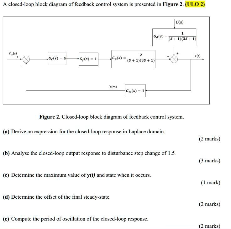
Solved A Closed Loop Block Diagram Of A Feedback Control System Is Closed loop block diagram.docx free download as word doc (.doc .docx), pdf file (.pdf), text file (.txt) or read online for free. closed loop control systems use feedback to automatically control and maintain the desired output level by comparing it to the actual output level and reducing any errors. Engine actual speed speed sensor fig. 1 3. basic closed loop system. block diagrams: because of their simplicity and versatility, block diagrams are often used by control engineers to describe all types of systems. a block diagram can be used simply to represent the composition and interconnection of a system. The basic input output relationship for a single block is: be connected in three basic forms:㬚崋 block diagram blocks can cascade parallel feedback we’ll next look at each of these forms and derive a single block equivalent for each. Figure: a block diagram for a feedback control system block: represents input output relationship of a system component either in the time domain (lti ode) or in the complex domain (transfer function) block diagram: interconnects blocks to represent a multi element system.

Closed Loop Feedback Control Block Diagram 23 Download Scientific The basic input output relationship for a single block is: be connected in three basic forms:㬚崋 block diagram blocks can cascade parallel feedback we’ll next look at each of these forms and derive a single block equivalent for each. Figure: a block diagram for a feedback control system block: represents input output relationship of a system component either in the time domain (lti ode) or in the complex domain (transfer function) block diagram: interconnects blocks to represent a multi element system. Dynamic behavior and stability of closed loop control systems in this chapter we consider the dynamic behavior of processes that are operated using feedback control. this combination of the process, the feedback controller, and the instrumentation is referred to as a feedback control loop or a closed loop system. Outline of topics what is control? the concept of closed loop feedback control a basic tool: the laplace transform using the laplace transform to characterize the time and frequency domain behavior of a system manipulating transfer functions to analyze systems how to predict performance of the controller.

Closed Loop Feedback Control Block Diagram 23 Download Scientific Dynamic behavior and stability of closed loop control systems in this chapter we consider the dynamic behavior of processes that are operated using feedback control. this combination of the process, the feedback controller, and the instrumentation is referred to as a feedback control loop or a closed loop system. Outline of topics what is control? the concept of closed loop feedback control a basic tool: the laplace transform using the laplace transform to characterize the time and frequency domain behavior of a system manipulating transfer functions to analyze systems how to predict performance of the controller.

Sensor Feedback Closed Loop Control Block Diagram Download

Closed Loop Feedback Control Block Diagram Download Scientific Diagram

Effects Of A Pid Controller In Closed Loop Feedback System Pdf