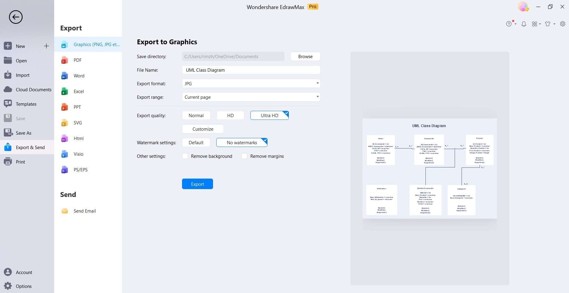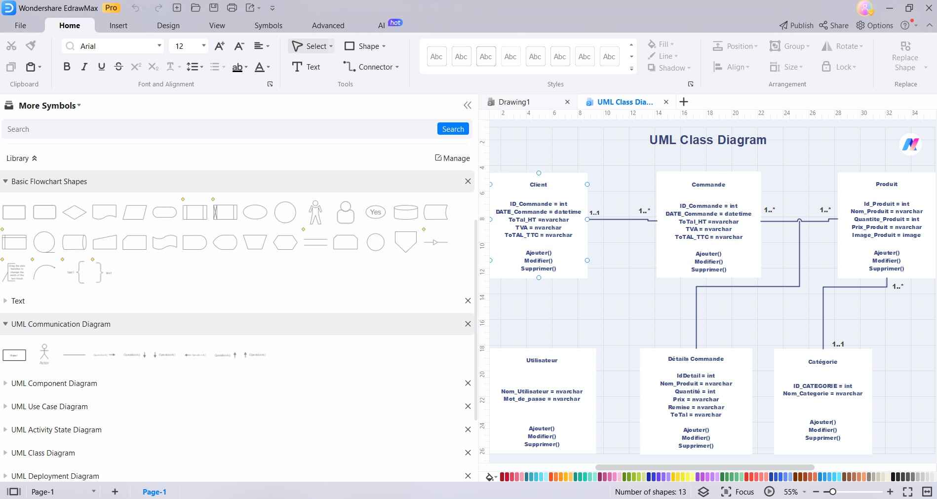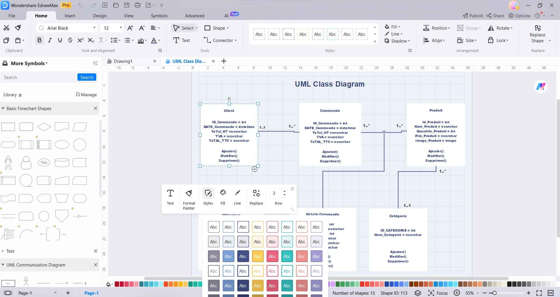
Basic Uml Class Diagram Data Flow Diagram Class Diagr Vrogue Co What's the difference? data flow diagram (dfd) and unified modeling language (uml) are both graphical tools used in software engineering to represent and analyze systems. however, they differ in their focus and level of detail. dfds primarily focus on the flow of data within a system, representing processes, data stores, and data flows. My current employer loves uml. i normally use bouml, which doesn't do non uml drawings. what is the uml drawing that corresponds to the data flow diagram? if there isn't one, what is the recommended uml diagram to present the corresponding data?.

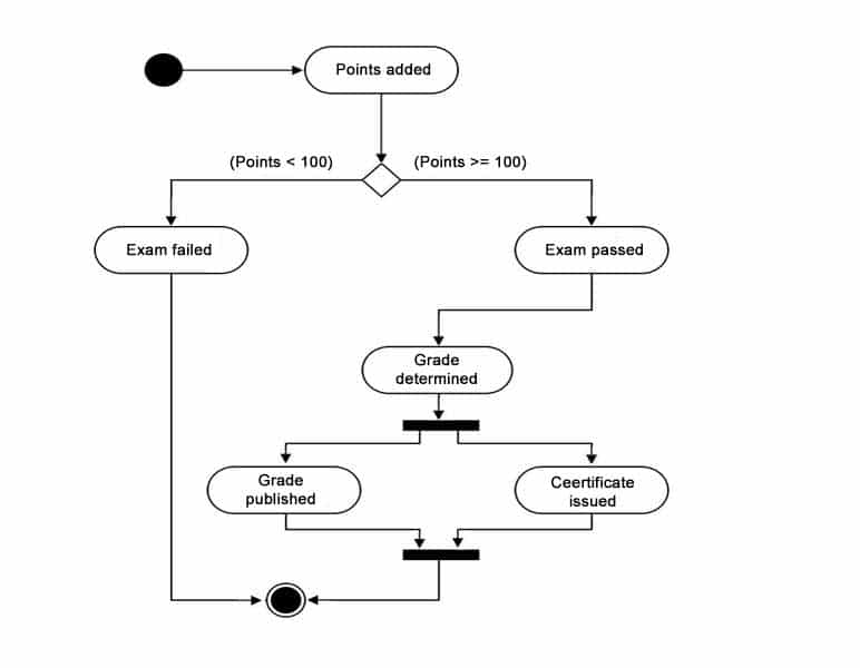
Diagram Process Flow Diagram Uml Full Version Hd Quality Diagram Uml Data flow diagrams (dfd) and unified modeling language (uml) are two widely used techniques in the field of software engineering for modeling and visualizing systems. while both methodologies serve the purpose of representing system structures and processes, they differ in their approaches and levels of abstraction. I suppose if one were to create the equivalent of a dfd diagram, it might be a uml activity diagram, but after trying so many tools for sysml and uml in the past, i began to wonder if just simple circles and arrows and boxes representing data stores are the way to go after all. Uml is used to visually represent systems in the form of diagrams, helping to understand the complexity of the system, evaluate and improve software architecture, and communicate with stakeholders. diagram type: dfd is a form of business process modeling notation that maps processes, inputs, outputs, and data storage. Data flow diagram (dfd) is the part of the ssadm method (structured systems analysis and design methodology), intended for analysis and information systems projection. data flow diagrams are intended for graphical representation of data flows in the information system and for analysis of data processing during the structural projection. data flow diagram often used in connection with human.

Create A Uml Data Flow Diagram A Comprehensive Guide Uml is used to visually represent systems in the form of diagrams, helping to understand the complexity of the system, evaluate and improve software architecture, and communicate with stakeholders. diagram type: dfd is a form of business process modeling notation that maps processes, inputs, outputs, and data storage. Data flow diagram (dfd) is the part of the ssadm method (structured systems analysis and design methodology), intended for analysis and information systems projection. data flow diagrams are intended for graphical representation of data flows in the information system and for analysis of data processing during the structural projection. data flow diagram often used in connection with human. In uml, data flows can be represented as parts of sequence diagrams or activity diagrams. a use case diagrams describes the interactions between the system you are building and the external world. in use case diagrams, this users external to the system are represented by actors. Uml 2.5 diagrams overview a uml diagram is a partial graphical representation (view) of a model of a system under design, implementation, or already in existence. uml diagram contains graphical elements (symbols) uml nodes connected with edges (also known as paths or flows) that represent elements in the uml model of the designed system. the uml model of the system might also contain other.

Create A Uml Data Flow Diagram A Comprehensive Guide In uml, data flows can be represented as parts of sequence diagrams or activity diagrams. a use case diagrams describes the interactions between the system you are building and the external world. in use case diagrams, this users external to the system are represented by actors. Uml 2.5 diagrams overview a uml diagram is a partial graphical representation (view) of a model of a system under design, implementation, or already in existence. uml diagram contains graphical elements (symbols) uml nodes connected with edges (also known as paths or flows) that represent elements in the uml model of the designed system. the uml model of the system might also contain other.

Create A Uml Data Flow Diagram A Comprehensive Guide

Create A Uml Data Flow Diagram A Comprehensive Guide