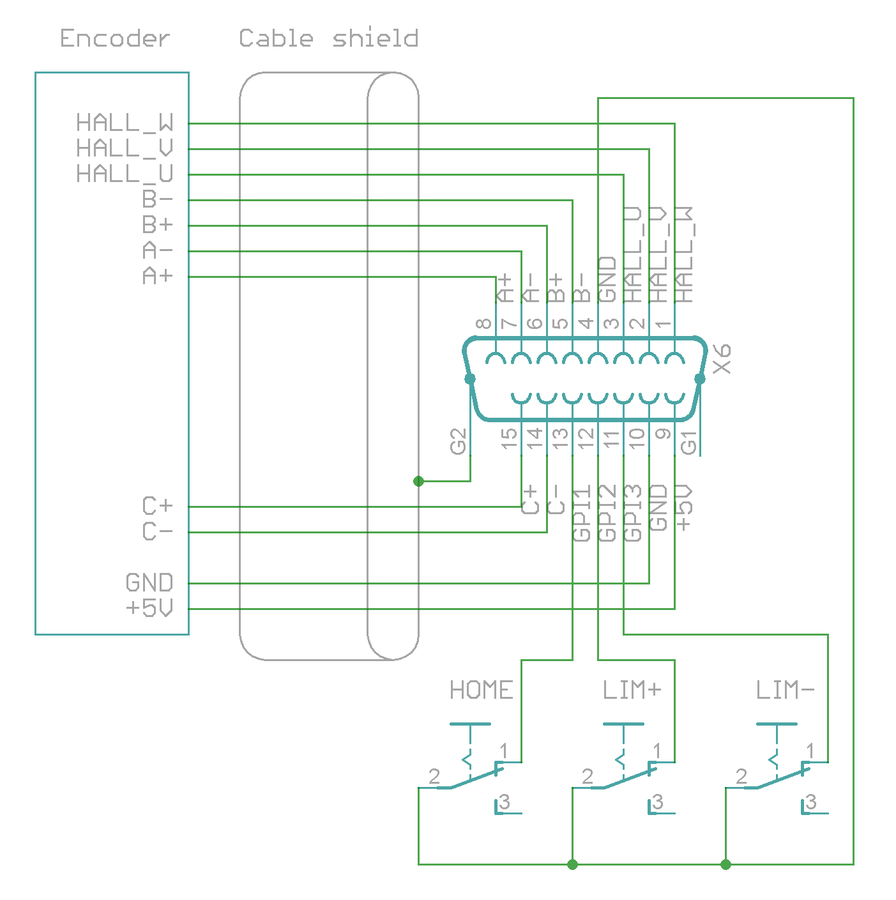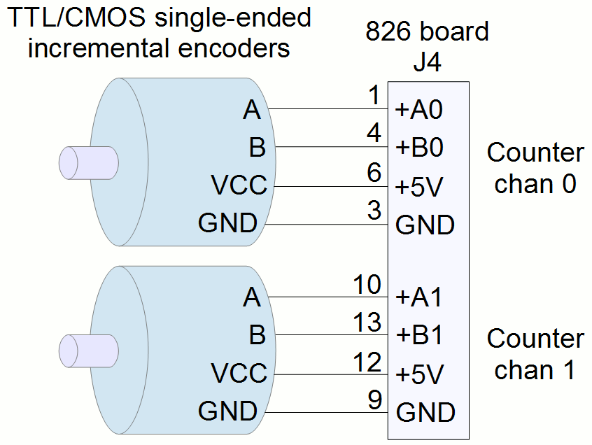
Encoder Pdf Electrical: check for loose wiring connections, ground loops, encoder outputs incompatible with the counter controller, a noisy power supply, electrical noise, proper termination of shields, or a combination of these problems. How to correctly wire and ground an encoder cable to optimize signal quality and avoid common wiring pitfalls such as noise, shaft currents and reverse phasing.

File Encoderwiring Full Png Granite Devices Knowledge Wiki Encoder wiring made simple fielding a successful product depends on choosing the right wiring scheme and output driver. encoders play an essential role in motion and automation, sending a constant stream of feedback to the motor drives and or controller to ensure that the load arrives at the specified position at the required time. Encoders normally get wired to an encoder block and then we use ethernet to connect to a vc1. in some instances, like on the smartconveyors the encoder does not go through a block and you need to terminate the end with a rj45 plug. below is the wiring diagram for encoder blocks. note the “1” and “8” on either side of the green terminals. these two numbers will help you know which side. Learn how rotary encoder sensor works, how to connect rotary encoder sensor to arduino, how to program arduino step by step. the detail instruction, code, wiring diagram, video tutorial, line by line code explanation are provided to help you quickly get started with arduino. Dynapar encoders come in a variety of models, each with their own unique wiring requirements. generally speaking, however, all dynapar encoders require a shielded twisted pair cable for proper operation.

Sew Encoder Wiring Diagram Learn how rotary encoder sensor works, how to connect rotary encoder sensor to arduino, how to program arduino step by step. the detail instruction, code, wiring diagram, video tutorial, line by line code explanation are provided to help you quickly get started with arduino. Dynapar encoders come in a variety of models, each with their own unique wiring requirements. generally speaking, however, all dynapar encoders require a shielded twisted pair cable for proper operation. In wiring, the cable plug at the output end of the encoder should be inserted into the corresponding port of the controller according to the connection method and voltage level. for the two signals a and b of the encoder, the common wiring methods are differential output and single ended output. differential output requires connecting a, a# and b, b# to the two input channels of the controller. Encoders provide quality measurements and long life when common sense, care, and accurate alignments are provided during installation. the following general guide lines will help to ensure a trouble free installation.

Incremental Encoder Wiring Diagram Wiring Diagram In wiring, the cable plug at the output end of the encoder should be inserted into the corresponding port of the controller according to the connection method and voltage level. for the two signals a and b of the encoder, the common wiring methods are differential output and single ended output. differential output requires connecting a, a# and b, b# to the two input channels of the controller. Encoders provide quality measurements and long life when common sense, care, and accurate alignments are provided during installation. the following general guide lines will help to ensure a trouble free installation.
Encoder Wiring Help
Incremental Encoder Wiring Diagram Circuit Diagram