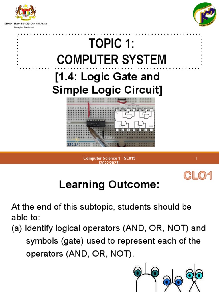
Logic Gate Pdf The logical symbol for two input and gate and the truth table is given below. This module introduces the basics of digital logic and shows how the whole of digital electronics depends on just seven types of logic gates, connected together with a minimum of additional components. combinations of logic gates then form circuits that can perform specific tasks within larger circuits or systems.

Logic Gate Pdf Logic Gate Cmos Boolean analysis of logic circuits boolean algebra provides a concise way to express the operation of a logic circuit formed by a combination of logic gates so that the output can be determined for various combinations of input values. Logic gates, boolean algebra and truth tables boolean algebra is the mathematical foundation of digital circuits. boolean algebra specifies the relationship between boolean variables which is used to design combinational logic circuits using logic gates. the truth table shows a logic circuit's output response to all of the input combinations. Logic gates what are logic gates? in the binary lesson, we discussed the switches inside a computer logic gates are the switches that turn on or off depending on what the user is doing! they are the building blocks for how computers work. Computer systems organization and programming digital design = from switches to logic gates to logic circuits.

Basic Logic Gate Pdf Logic gates what are logic gates? in the binary lesson, we discussed the switches inside a computer logic gates are the switches that turn on or off depending on what the user is doing! they are the building blocks for how computers work. Computer systems organization and programming digital design = from switches to logic gates to logic circuits. The basic logic gates are the inverter (or not gate), the and gate, the or gate and the exclusive or gate (xor). if you put an inverter in front of the and gate, you get the nand gate etc. one of the common tool in specifying a gate function is the truth table. Figure 3 18 standard logic symbols for the or gate showing two inputs (ansi ieee std. 91 1984 std. 91a 1991). up for reprogrammable logic device g pin numbers and basic a 54 74hc00a quad 2 input nand gate. the 54 prefix indicates military grade and the prefix indicates commercial grade.

Logic Gates Pdf Logic Gate Electronic Circuits The basic logic gates are the inverter (or not gate), the and gate, the or gate and the exclusive or gate (xor). if you put an inverter in front of the and gate, you get the nand gate etc. one of the common tool in specifying a gate function is the truth table. Figure 3 18 standard logic symbols for the or gate showing two inputs (ansi ieee std. 91 1984 std. 91a 1991). up for reprogrammable logic device g pin numbers and basic a 54 74hc00a quad 2 input nand gate. the 54 prefix indicates military grade and the prefix indicates commercial grade.

Logic Gate Pdf

Logic Gate 2 Pdf

1 4 Lecture Logic Gate And Simple Logic Circuit 20222023 Pdf