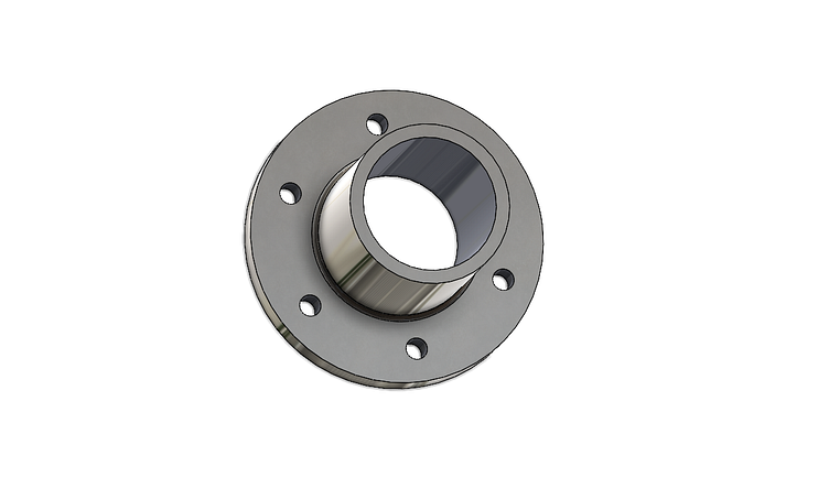
Mechanical Coupling Design In Solidworks Solidworks Tutorial #mechanicaldrawing #mechanicalparts #solidworkstutorial this is the solidwork tutorial to design a frange coupling. the use of coupling is very large in mechanical engineering. In this tutorial, we will discuss how to design a mechanical coupling in solidworks. this tutorial will cover the following topics: defining the part size and position estimating component forces and moments designing the coupling using linear static analysis making the part model ready for manufacturing mechanical coupling design in.

An Image Of A Computer Screen With A Drawing Of A Barrel On The Left Side This tutorial was asked by one of my subscriber syed musab ahmed who was facing some difficulties in solidworks assembly and solidworks toolbox. in this tutorial, we will model, assemble & animate basic flange coupling in solidworks2020. here we will do the following things: 1) part modeling 2) hole wizard 3) sw toolbox 4) appearance 6) parts. Abstract engineers can utilize the solidworks api and macro functionality to construct custom programs and applications (macros) that can be used to automate numerous cad activities. this paper illustrates work on design automation of mechanical components like nuts, bolts, screws, and flange coupling. Dive into solidworks with our beginner friendly tutorial on creating a unprotected flange coupling. follow along as we guide you through part design and assembly, covering essential techniques for. Flange coupling assembly in solidworks how to make a flange coupling assembly in solidworks hello friends my name is pawan kumar and welcome to solidworks projects channel. in this channel you learn about solidwork software. dimensions pdf link :.

Coupling Solidworks Tutorial Solidworks Tutorial Solidworks Dive into solidworks with our beginner friendly tutorial on creating a unprotected flange coupling. follow along as we guide you through part design and assembly, covering essential techniques for. Flange coupling assembly in solidworks how to make a flange coupling assembly in solidworks hello friends my name is pawan kumar and welcome to solidworks projects channel. in this channel you learn about solidwork software. dimensions pdf link :. The document explains the process of creating a miter flange in solidworks 2020, detailing the requirements for sketches and the steps to define bending locations. it covers the use of dimensions, gap management between bends, and the final export of the design as a dxf file for cnc machining. the miter flange feature allows for the addition of multiple flanges to the edges of a sheet metal. Find your solidworks training course, solidworks tutorial, cswp solidworks certification course. we have compiled the best courses so that you don’t have to waste a minute and can get started straight away!.

Flange Coupling Assembly Step Iges Solidworks 3d Cad Model Grabcad The document explains the process of creating a miter flange in solidworks 2020, detailing the requirements for sketches and the steps to define bending locations. it covers the use of dimensions, gap management between bends, and the final export of the design as a dxf file for cnc machining. the miter flange feature allows for the addition of multiple flanges to the edges of a sheet metal. Find your solidworks training course, solidworks tutorial, cswp solidworks certification course. we have compiled the best courses so that you don’t have to waste a minute and can get started straight away!.

Flange Coupling 3d Cad Model Library Grabcad

Solution Flange Coupling Machine Design And Mechanical Drawing Notes

Frange Coupling Concept By Jayden S On Dribbble