Solved Consider The Block Diagram Below Obtain The Closed Chegg The (linearized) closed loop block diagram for the pll is shown in fig. 1. the objective is to design the controller k (8) and the post filter h (8) so that y (t) accurately tracks r (t), according to the specifications given below. For example, remember from the rst lecture that the basic block diagram of a feedback control system looks like this: we will frequently want to manipulate block diagram representations of systems in order to nd the overall transfer function of the system in terms of the transfer functions of the individual components or subsystems.

Solved Question 1 Block Diagram Reduction And Closed Loop Chegg Figure: a block diagram for a feedback control system block: represents input output relationship of a system component either in the time domain (lti ode) or in the complex domain (transfer function) block diagram: interconnects blocks to represent a multi element system. This document discusses block diagram reduction techniques. it provides steps to simplify a block diagram and determine the closed loop transfer function. the steps include applying rules such as combining blocks in series and parallel, moving summing points, interchanging summing points, eliminating feedback loops by considering the forward or feedback loop transfer function to be unity. an. This article explains the various rules that must be followed while reducing a complex block diagram into a simple one so as to make system analysis easy. also an example is provided to help you to practically understand the rules of block diagram reduction. A way to cope with the system parameter changes, and a way to reduce the impact of those changes on the system output, is to form a closed loop system configuration, also known as the system feedback configuration. we can feed back the system output and form the closed loop around the system as presented in.

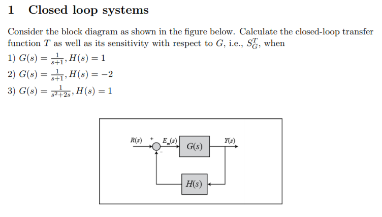
Solved 1 Closed Loop Systems Consider The Block Diagram As Chegg This article explains the various rules that must be followed while reducing a complex block diagram into a simple one so as to make system analysis easy. also an example is provided to help you to practically understand the rules of block diagram reduction. A way to cope with the system parameter changes, and a way to reduce the impact of those changes on the system output, is to form a closed loop system configuration, also known as the system feedback configuration. we can feed back the system output and form the closed loop around the system as presented in. 4. terminology fig. 9, block diagram components regarding the closed loop control system shown in fig. 9, we can define the following terms; plant: a physical object to be controlled. the plant g3 (s), is the controlled system, of which a particular quantity or condition is to be controlled. Figure p8.13 shows the block diagram of a closed loop control of a linearized magnetic levitation system (galvão, 2003). r (s) c (s) g (s) a 92 12 figure p8.13 linearized magnetic levitation system block diagram assuming a = 1300 and n = 860, draw the root locus and find the range of k for closed loop stability when: a.

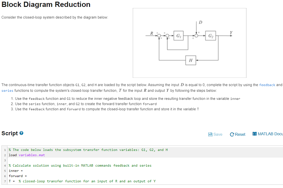
Solved Block Diagram Reduction Consider The Closed Loop Chegg 4. terminology fig. 9, block diagram components regarding the closed loop control system shown in fig. 9, we can define the following terms; plant: a physical object to be controlled. the plant g3 (s), is the controlled system, of which a particular quantity or condition is to be controlled. Figure p8.13 shows the block diagram of a closed loop control of a linearized magnetic levitation system (galvão, 2003). r (s) c (s) g (s) a 92 12 figure p8.13 linearized magnetic levitation system block diagram assuming a = 1300 and n = 860, draw the root locus and find the range of k for closed loop stability when: a.

Solved Figure 1 Shows The Closed Loop Block Diagram For A Chegg

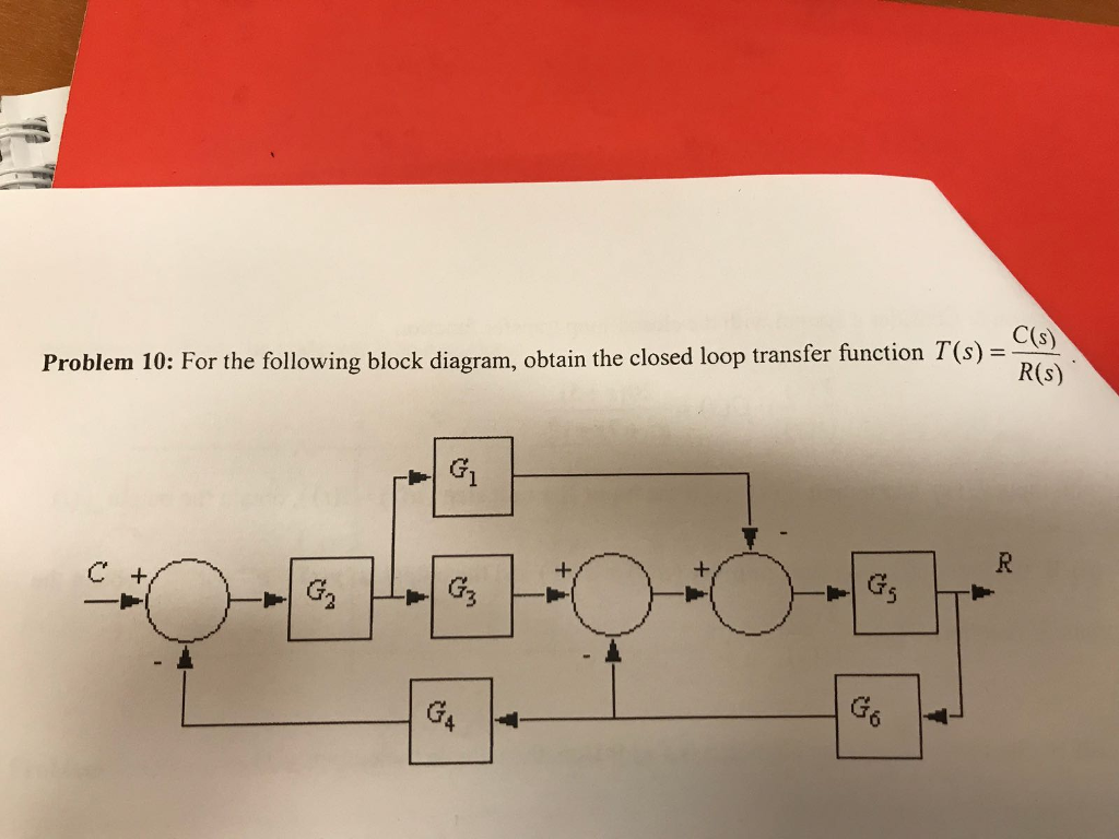
Solved Problem 10 For The Following Block Diagram Obtain Chegg