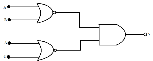
Wiring Diagram Logic Gates Circuit Diagram As we continue to see technology advance, wiring diagrams for logic gates are becoming more complicated. in order to stay ahead of the game, engineers need to create accurate and reliable diagrams that clearly show the circuit’s logical structure. The logic gates are the building blocks of digital circuits. a logic gate has one output, but one or more inputs. the output signal appears only for certain combinations of input signals. there are three basic logic gates: or gate, and gate, not gate. each logic gate is indicated by a logical symbol and its function is described either by a ‘truth table’ or by a ‘boolean expression.

Wiring Diagram Logic Gates Circuit Diagram Simple logic gates and circuits: logic gates are some of the basic building blocks of digital logic circuitry. in this instructable we will talk about a few of the simplest of these devices, and see some of the fun things you can do with them. so what are logic gates? logic ga…. Circuit diagram is a free application for making electronic circuit diagrams and exporting them as images. design circuits online in your browser or using the desktop application. Logic circuits and wiring diagrams are an essential part of modern electronics. logic circuits provide the functionality necessary to control a variety of devices while wiring diagrams provide a graphical representation of the circuit and its components, making it easier to design and construct the circuit. Logic gates are the heart and soul of digital circuit designs. with logic gate circuit diagram examples, engineers and developers can quickly and accurately create complex circuits that do exactly what they need them to do.

Logic Gates Wiring Diagram Wiring Diagram Logic circuits and wiring diagrams are an essential part of modern electronics. logic circuits provide the functionality necessary to control a variety of devices while wiring diagrams provide a graphical representation of the circuit and its components, making it easier to design and construct the circuit. Logic gates are the heart and soul of digital circuit designs. with logic gate circuit diagram examples, engineers and developers can quickly and accurately create complex circuits that do exactly what they need them to do. Logic circuit diagrams are an essential part of any engineering project. by using them, you can easily illustrate the various components of a system, how they interact with one another, and how logic gates are used to control the flow of signals within the system. Review how the wiring of your circuit matches the schematic diagram below, referencing the and gate you are using in the 74xx08 chip. (the dotted lines are connected vertically inside the breadboard because the wires you plug into the breadboard are in the same column as the respective pins off the chip.).

Schematic Diagram Logic Gates Circuit Diagram Logic circuit diagrams are an essential part of any engineering project. by using them, you can easily illustrate the various components of a system, how they interact with one another, and how logic gates are used to control the flow of signals within the system. Review how the wiring of your circuit matches the schematic diagram below, referencing the and gate you are using in the 74xx08 chip. (the dotted lines are connected vertically inside the breadboard because the wires you plug into the breadboard are in the same column as the respective pins off the chip.).

Internal Circuit Diagram Of Logic Gates

Diagram Circuit Diagram Using Logic Gates Wiringschema Com